
Starting with Creo 4.0, you can place a hole using an axis or point and a surface as references, even if – the axis is not normal to the surface or the point is not on the surface.
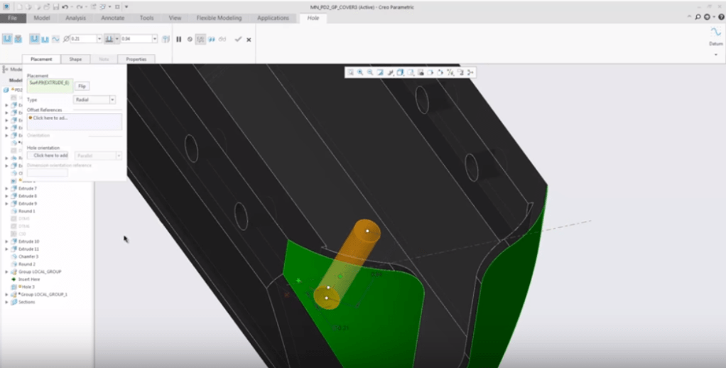
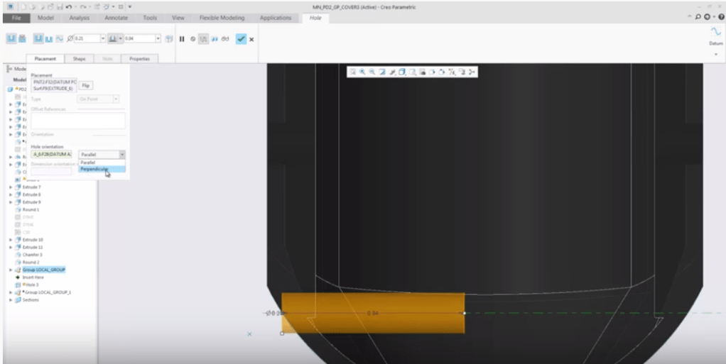
Note: you can define the orientation of the hole regardless of how the hole is placed. When placed on non-axial references, you can specify the hole orientation. The hole axis can then be defined to be parallel or perpendicular to the selected reference orientation.
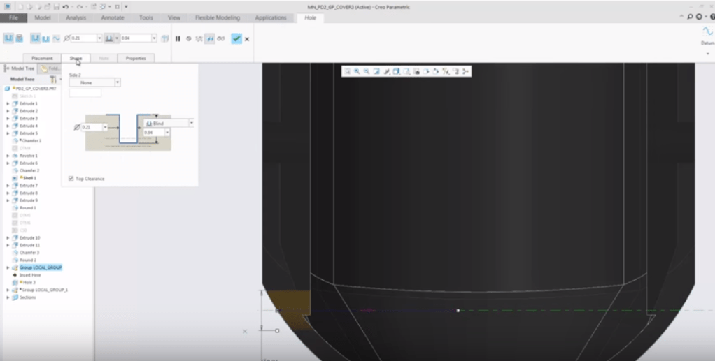
Holes can be created with top clearance. The diameter of the hole, countersink, or counterbore is used to create a cylinder that cuts through the solid geometry. This avoids situations where holes are partially or totally buried in the solid geometry. You can control the default top clearance with a configuration option
Hole reference pattern capabilities support hole orientation references together with placement references. As a result, you can create hole reference patterns by driving placement and orientation for each pattern member

About Punditas
Punditas delivers Artificial Intelligence(AI) driven content for PTC Creo Parametric and other Enterprise Application Softwares. Punditas AI engine taps into 100’s of internal & external repositories for Creo Parametric to Discover, Curate & Deliver pertinent Tips, Tricks, Tutorials, Best Practices, etc. up to 5 perspectives of content based on each Creo Users style and preference. To learn more about Punditas, visit https://www.punditas.com
Content source: PTC

Leave a comment