Using dimension-driven patterns help specify multiple occurrences of a component in an assembly. The dimension-driven pattern uses assembly constraint dimensions such as Distance or Angle Offset offset values. The rules for creating a dimension-driven pattern are the same as those for feature patterning in Part mode.
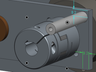
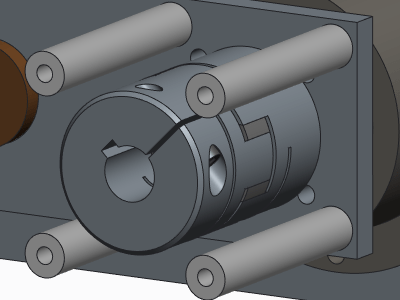
Example below – A component assembled with a distance constraint is patterned using the distance as the driving dimensions. (note this part is assembled once and patterned)

To assemble components to a Dimension Pattern
Step 1: click  Assemble or drag a component from the browser into the active assembly session
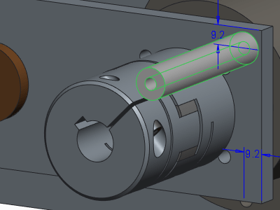
Step 2: Place the component with at least one offset type constraint. To create the pattern, you must specify the offset values that you want to use as references
Step 3. Select the component in the Model Tree and do either of the two below to open Pattern tab
- Click
 Pattern
 - Right-click in the graphics window and choose Pattern from the shortcut menu.
Step 5. Click the Dimensions tab, select a dimension in the assembly, and enter an incremental value, or drag the handle to the required location

About Punditas
Punditas delivers Artificial Intelligence(AI) driven content for PTC Creo Parametric and other Enterprise Application Softwares. Punditas AI engine taps into 100’s of internal & external repositories for Creo Parametric to Discover, Curate & Deliver pertinent Tips, Tricks, Tutorials, Best Practices, etc. up to 5 perspectives of content based on each Creo Users style and preference. To learn more about Punditas, visit https://www.punditas.com
Content source: PTC

Leave a comment