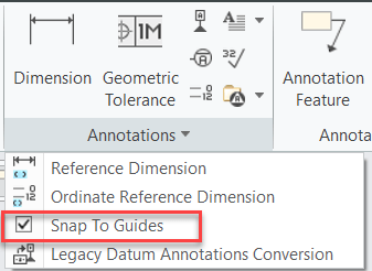
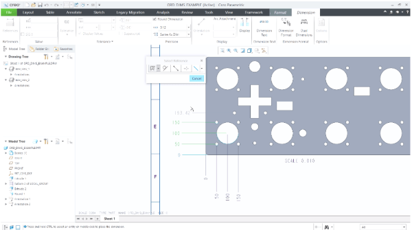
Starting with Creo 7.0, there's better control over the placement of ordinate dimensions that are created in models and drawings. Prior to this Creo 7.0 release, when creating ordinate dimensions per ANSI standards, these dimensions would get placed when they are aligned with the baseline. However, this can now be controlled using "default_ansi_ord_dim_aligned" config option.... Continue Reading →
Have you tried to accurately remove hidden lines for intersecting components in Creo?
If you have a part with interfering bodies or an assembly with interfere hidden lines removed. You might also want to see a drawing for a part or assembly with interfering parts or components, correctly with hidden lines removed. Starting with Creo 7.0, you can use the below config option to accurately remove the Hidden... Continue Reading →
How to control snapping of normal and tangent placement of leader annotations in Creo?
When you place a leader annotation on an edge, the normal or tangent leaders appear as soon as the cursor position is beyond the snapping angle threshold. You may turn off this snapping in order to place a leader annotation very close to a normal or a tangent placement without the snapping. With Creo 7.0.1.0,... Continue Reading →
Did you know that you can control the display of geometry reps in Creo?
With Creo 7.0, you can control the display of representation geometry without setting defined appearances or appearance states. This makes it easier to work with different types of geometry representations. You can select or clear the Boundary (B-rep) and Mixed check boxes to hide or show the type of geometry representation. To set the transparency for each representation type,... Continue Reading →
Did you know about improvements in Creo for placement of ordinate dimensions?
Starting with Creo Parametric 7.0.0.0, there's better control over the placement of ordinate dimensions that are created in models and drawings. This can be done by setting the detail option, default_ansi_ord_dim_aligned. Your options for this option are Yes - Align with the baseline dimensionNo - Stay at the position of the pointer until you place it. When... Continue Reading →
Do you like the improved appearance of handles, text, dimensions, and lines in Creo?
Starting with Creo 5.0, the appearance of handles, text, dimensions, and lines (2D and 3D) displayed in the graphics area have improved visibility. In addition, Lines Anti-Aliasing and Text Anti-Aliasing can also be controlled. For example - you can set Lines Anti-Aliasing to On even if the Anti-Aliasing is set to Off. I think these are improvements are definitely useful. What are your thoughts?... Continue Reading →
Did you know that applying drafts to models containing rounds and chamfers is vastly enhanced in Creo?
With Creo 5.0, PTC enhanced the ability to apply drafts to design models containing rounds and chamfers. Select surfaces as references in the Draft surfaces collector of the draft feature. Rounds and chamfers are automatically detected and highlighted in a different color. Rounds and chamfers are then handled as they are in the Creo Parametric Flexible Modeling environment If... Continue Reading →
How to quickly find similar geometric shapes and surfaces in Creo?
Starting with Creo Parametric 4.0, you can quickly find rounds, chamfers , sheet metal design objects from within a single, easy-to-use search tool. The Geometry Search tool allows searches based on geometry and design intent to Creo Flexible Modeling. Searches can be based on a seed surface or be defined without a seed. Search results appears in the Found... Continue Reading →
Did you know that you can assign different appearances to the same component in Creo?
We can now capture multiple appearance combinations for the same part and assembly and easily switch between appearance variants. Use Appearance state instead of Combined state. To do this goto View Manager to set the appearance state of your component. You can also use appearance states inside combined states and switch between... Continue Reading →
Did you know that you can create a midplane between selected references in Creo?
Datum Plane tool in Creo provides an option to create a mid-plane between selected references. The enhancement has made it easier to understand how constraints can be changed. Also its faster to define datum planes especially in conjunction with operations such as Mirror. Depending on the geometric situation, the midplane can be created parallel to... Continue Reading →