Starting with Creo Parametric 4.0, you can quickly find rounds, chamfers , sheet metal design objects from within a single, easy-to-use search tool. The Geometry Search tool allows searches based on geometry and design intent to Creo Flexible Modeling. Searches can be based on a seed surface or be defined without a seed. Search results appears in the Found... Continue Reading →
Did you know about these hole placement enhancements in Creo?
Starting with Creo 4.0, you can place a hole using an axis or point and a surface as references, even if - the axis is not normal to the surface or the point is not on the surface. Note: you can define the orientation of the hole regardless of how the hole is placed. When... Continue Reading →
How do you drag surface finishes beyond placement surface in Creo?
In Creo, if the placement surface is planar, then you can drag surface finishes in the XY direction beyond the placement surface. An extension line is created in the XY-direction when you drag the surface finish off the reference surface as shown below You can drag the surface finish in the Z-direction even when it... Continue Reading →
Have you tried splitting surfaces in Creo?
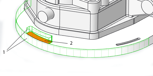
In Creo, some shape surface sets that are selected for removal contain surfaces that are shared by shapes included in the surface set, and shapes that are not included in the surface set. The system automatically splits these shared surfaces so that only the portions of the shared surfaces that belong to the selected shapes... Continue Reading →
How to trim a quilt in Creo using curves?
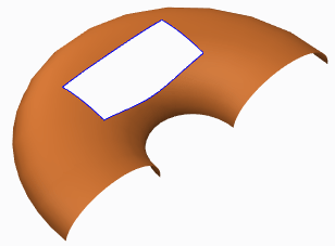
Quilts in Creo can be trimmed in a few ways (see below). Adding a cut or slot as you do to remove material from solid featuresTrimming the quilt at its intersection with another quilt or to its own silhouette edge as it appears in a certain viewFilleting corners of the quiltTrimming along a datum curve... Continue Reading →
Do you know how to flip the normal direction of a loft surface in Creo?
With Creo 5.0 release, you can flip the normal direction of a loft surface from one side of a boundary curve to the other side. However, in previous releases of Creo, you could not control the direction of the normal connection of a loft surface where the boundary curve is planer. As a result, the... Continue Reading →
Punditas AI Advisor now supports Creo 6.0.4.0
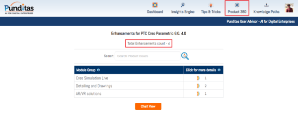
PTC released Creo 6.0.4.0 recently. Punditas AI Advisor now supports this latest version of Creo 6.0.4.0. Punditas AI allows users to learn more about “How”, What” and “Why” of these enhancements through Product 360 module. The picture below shows the Module groups and the corresponding enhancements added within each group. To try this out, please... Continue Reading →
Did you know about improved control of visibility by object type in Creo?
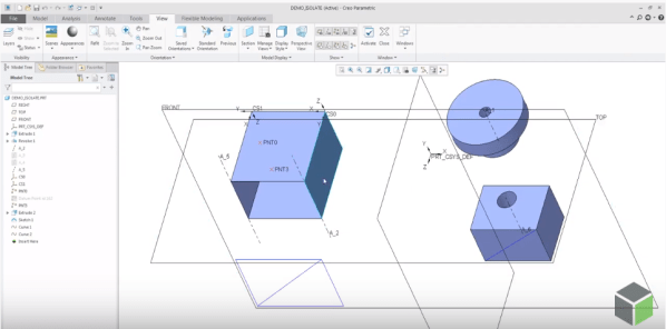
PTC has improved the control of visibility by object type in Part and Assembly modes by adding 2 commands - Show All or Show All Except There are 3 ways to access these new, additional commands for Showing and Hiding objects 1. From View Tab 2. Mini toolbar from graphics area 3. From Model Tree... Continue Reading →
How to assemble components to a Dimension Pattern in Creo?
Using dimension-driven patterns help specify multiple occurrences of a component in an assembly. The dimension-driven pattern uses assembly constraint dimensions such as Distance or Angle Offset offset values. The rules for creating a dimension-driven pattern are the same as those for feature patterning in Part mode. Example below - A component assembled with a distance constraint is patterned using... Continue Reading →
Did you know that defining radial dimensions in Creo is more intuitive now?
PTC has improved the workflow for creating radial dimensions. The Typical creation of radial dimension provides upto 4 flip states that represents different witness line and arrow configurations. Starting with Creo 5.0, the definition of flip states is improved to provide better default states, depending on the position of the pointer. This provides visual feedback... Continue Reading →