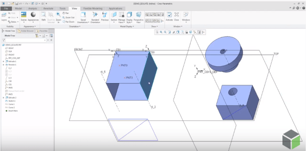
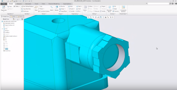
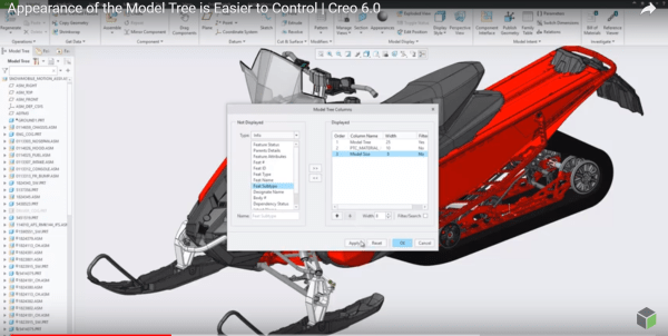
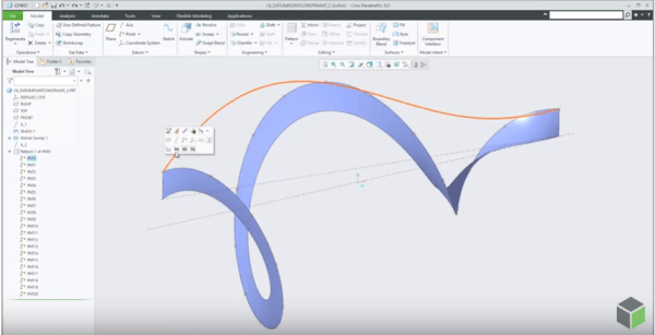
PTC has improved the control of visibility by object type in Part and Assembly modes by adding 2 commands - Show All or Show All Except There are 3 ways to access these new, additional commands for Showing and Hiding objects 1. From View Tab 2. Mini toolbar from graphics area 3. From Model Tree... Continue Reading →
How to assemble components to a Dimension Pattern in Creo?
Using dimension-driven patterns help specify multiple occurrences of a component in an assembly. The dimension-driven pattern uses assembly constraint dimensions such as Distance or Angle Offset offset values. The rules for creating a dimension-driven pattern are the same as those for feature patterning in Part mode. Example below - A component assembled with a distance constraint is patterned using... Continue Reading →
Did you know that defining radial dimensions in Creo is more intuitive now?
PTC has improved the workflow for creating radial dimensions. The Typical creation of radial dimension provides upto 4 flip states that represents different witness line and arrow configurations. Starting with Creo 5.0, the definition of flip states is improved to provide better default states, depending on the position of the pointer. This provides visual feedback... Continue Reading →
Did you know that you can assign different appearances to the same component in Creo?
We can now capture multiple appearance combinations for the same part and assembly and easily switch between appearance variants. Use Appearance state instead of Combined state. To do this goto View Manager to set the appearance state of your component. You can also use appearance states inside combined states and switch between... Continue Reading →
Did you know that mirroring of features in Creo is improved?
Starting with Creo Parametric 5.0 release, the workflow for mirroring of features is enhanced. Mirror workflow provides an intuitive preview and increased flexibility during redefinition. Also, Mirror tool is faster in definition and re-definition of mirror feature. Preview in the graphics windows is available during creation or redefinition of feature for quick visual feedback on... Continue Reading →
Did you know that you can create a midplane between selected references in Creo?
Datum Plane tool in Creo provides an option to create a mid-plane between selected references. The enhancement has made it easier to understand how constraints can be changed. Also its faster to define datum planes especially in conjunction with operations such as Mirror. Depending on the geometric situation, the midplane can be created parallel to... Continue Reading →
Did you know that you can now control the appearance of Model Tree in Creo?
I think this is a neat enhancement in Creo. With Creo 6.0 release, the Model Tree appearance can be controlled and configured by users Setting Up the Model Tree You can define the width of the model tree - add columns and keep the Model Tree column at the default width or the width you... Continue Reading →
What is Chart Tool in Creo Parametric and how does it work?
A new modernized Chart tool replaces Graph tool starting with Creo Parametric 6.0 release. Chart tool has more options and provides more control over the chart settings. Chart-Tool can be used to view and customize different types of graphs. Once the graph is displayed, the graph can be changed for border colors, fonts, background colors,... Continue Reading →
How to project a Datum Point onto a planar surface in Creo Parametric?
In Creo Parametric 6.0, the Datum point feature is enhanced. A constraint option is added to the datum point feature to project a datum point, a vertex or a curve endpoint onto a planar surface, datum plane, straight edge line or axis. Also, note that datum points created with project constraints can also be used... Continue Reading →
Creo Patterning
Mark Ganzer@Toro has done an excellent job covering Patterning in Creo - Basics, Performance & Tips in one his presentations. Here are some excerpts from his slide deck. Check out the Tips (below) in particular ... Continue Reading →